Replacing syringes, tubing, and valves in your C-Trap
Technical Support Team
June 23, 2026
(last updated)
0
min
Abstract
This guide provides step-by-step instructions for replacing syringes, tubing, and valves for the Microfluidics Module of your C-Trap or m-Trap. Procedures include material handling, tubing specifications, assembly and disassembly of tubing-to-valve connections, valve replacement, syringe maintenance, and leak testing with troubleshooting. Following these instructions helps maintain cleanliness, ensure correct installation of fluidic components, and minimizes the risk of leaks during operation.
1.1 Always wear clean gloves or sanitize them with ethanol before handling syringes, tubing, or valves.
1.2 Ensure the system contains MilliQ water only and no harmful substances before starting.
1.3 Remove valves from the automated fluidics unit before replacing tubing. It is not always necessary but strongly recommended for easier manipulation.
1.4 Handle threaded connections carefully and avoid over-tightening.
1.5 Tubing should be replaced every 6 months in order to guarantee the best experimental conditions and highest data quality. The necessary materials are included in C-Trap connection kit and can be purchased via the LUMICKS store.
2. Materials
Tubing: material is FEP (Fluorinated Ethylene Propylene, refer to FEP chemical resistance charts for compatibility). Available inner diameters for the C-Trap Microfluidics Module:
Small: 0.1 mm (0.004") – Channels 1–5 (PM-1148-F)
Medium: 0.25 mm (0.01") – Channel 6 (1527L)
Syringes: Terumo Luer Lock, 3 mL (remove plunger before use).
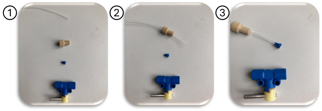
3. Connecting tubing to valves
Cut the small size tubing with a tube cutter. Ensure a clean, perpendicular cut.
Insert tubing through the beige tubing connection nut.
Place a blue tubing connection ferrule on the tubing with the wide part oriented toward the cut end.
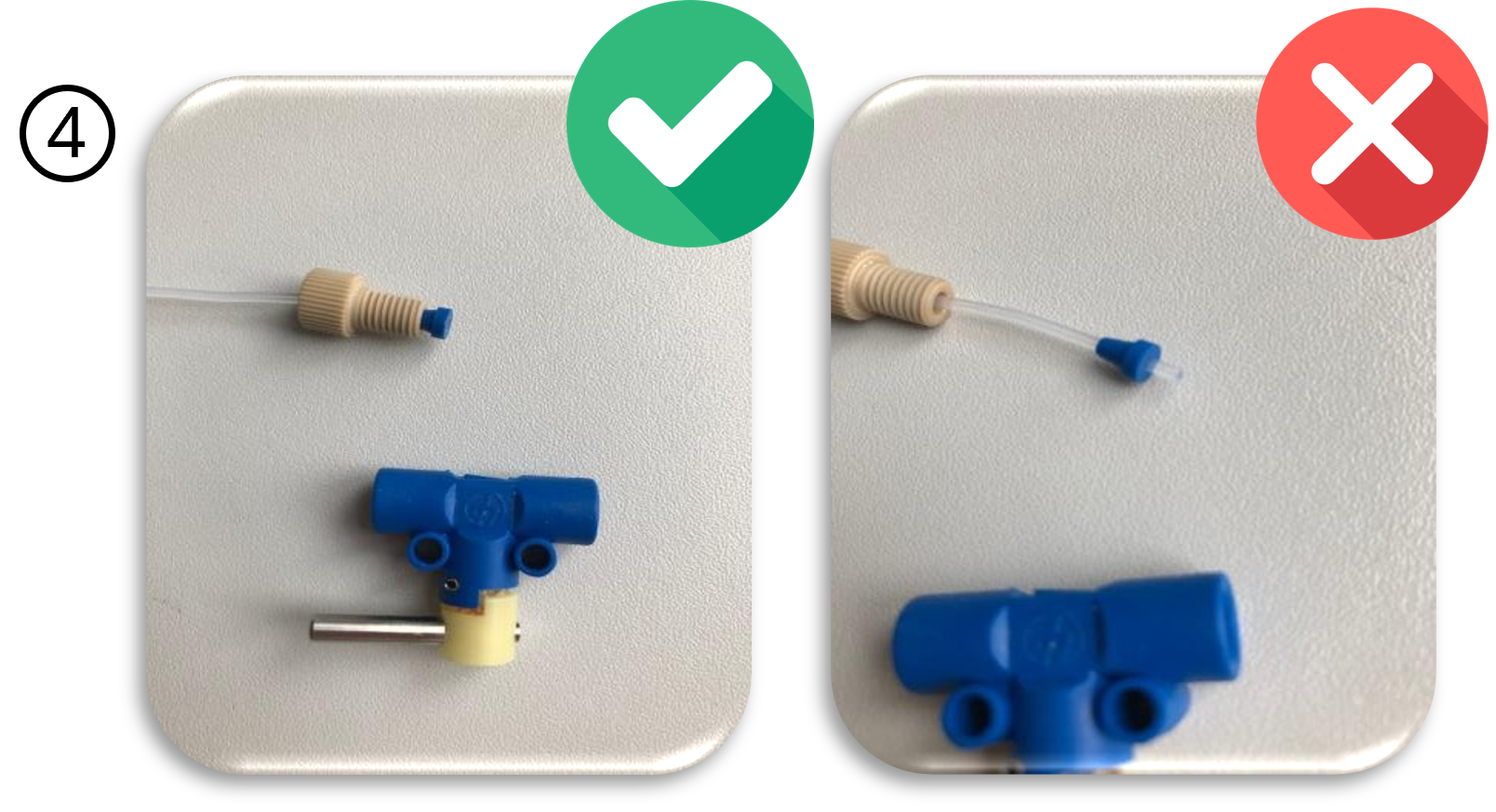
Ensure the tubing end is flush with the ferrule surface (not protruding or recessed), otherwise liquid might get caught there.
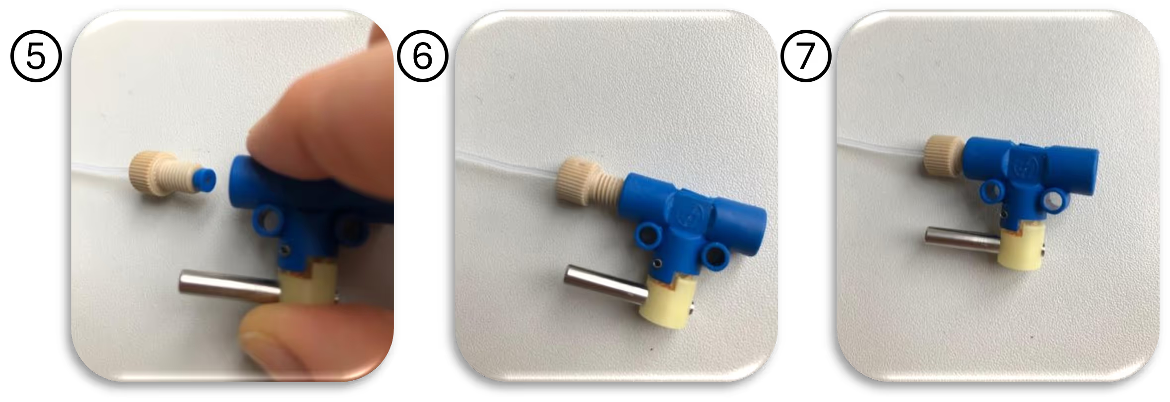
Insert the assembly into the valve entry, keeping the tubing alignment intact (cut end in plane with blue inlet surface).
Tighten the beige tubing connection nut fully, until it cannot be turned anymore. This should secure the tubing and ferrule without rotation.
Once assembled, the tubing, the beige tubing connection nut, and the blue tubing connection ferrule screw remain fixed together when unscrewed.
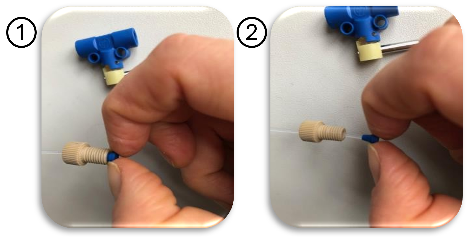
4. Disconnecting tubing from valves
4.1 Unscrew the beige tubing connection nut. The tubing and ferrule will rotate together during removal.
4.2 To separate, insert a fingernail or tool between the ferrule and screw, then slide the ferrule relative to the screw.
4.3 Replace tubing or ferrule as needed and reassemble, following Section 3.
Disconnecting tubing from valves.
5. Valve removal and attachment
5.1 Detaching a valve
In Bluelake or the Microfluidics Module applet, close all valves and open only the valve to be removed.
Release fluidic pressure.
Unscrew the valve mounting screws.
Remove the valve.
5.2 Attaching a valve
In Bluelake or the Microfluidics Module applet, close all valves and open the valve to be attached.
Release fluidic pressure.
Verify that the valve channel is in its open position before reinstallation.
Position the valve and secure it with mounting screws.
6. Syringe handling
6.1 We recommend replacing the syringes during every cleaning protocol. Please refer to the recommended cleaning protocol on the LUMICKS store.
6.2 To replace, unscrew the syringe from the transparent female Luer connector. In legacy systems, syringes may connect via blue manual valves.
6.3 Store plungers separately in a clean container for manual unclogging when required. Ensure that both the specific channel valve and the outlet valve are open during unclogging.
7. Leak testing procedure
7.1 Fill all syringes with water or another safe liquid, ensuring equal levels.
7.2 Flush all channels simultaneously.
7.3 Monitor fluid levels across all syringes; levels should decrease uniformly during flushing. Uneven drops indicate potential leaks.
8. Troubleshooting fluidic leaks
When performing leak testing, observe carefully where liquid emerges. Use the guide below to identify the source and apply corrective action. Always retest after implementing a step before moving to the next.
| Observation | Try the following |
| --- | --- |
| Leaks at Syringe Connection: Syringe empties rapidly; liquid accumulates beneath the syringe. | - Verify that the syringe is properly seated in the transparent female Luer connector. Retighten by hand, ensuring a snug fit without over-torque. - Check that the transparent female Luer connector is securely threaded into the valve (older systems) or adapter (newer systems). Retighten if needed. - Inspect the syringe tip and transparent female Luer connector for cracks, wear, or deformation. Replace defective parts. |
| Leaks at Tubing–Valve Interface: Faster drop in syringe volume, liquid pooling under tubing connection. | - Unscrew the beige tubing connection nut. Advance tubing ~1 mm through the blue tubing connection Ferrule so that it protrudes slightly. Retighten firmly. - Replace the ferrule if it shows signs of wear, deformation, or leakage after reseating. - Confirm that tubing is not damaged (kinks, ovalization, scratches). Replace if necessary. |
| Leaks at Valve Body: Drops emerging from the metallic housing of the valve or directly beneath it. | - First, repeat corrective actions from Section 8.2. - If the issue persists, replace the valve entirely. |
| Leaks at Valve Housing (Autofluidics Unit): Liquid visible between vertical and horizontal components of the Autofluidics unit, not directly near tubing. | - Open the affected valve without pressure applied. - Using a hex key, loosen the two mounting screws and remove the valve. - Carefully clean residual liquid inside the cavity with a lint-free swab or absorbent pad. - Perform Section 8.2 corrective actions on tubing/ferrule. - Test valve outside the Autofluidics unit under pressure. Reinstall only if the leak is fully resolved. |
| Leaks at Flow Cell: Liquid droplets or pooling on top of the flow cell. | - Verify that the waste outlet (Channel 6) is open during flushing. - Reseat the tubing in the flow cell holder, ensuring proper insertion depth. - Check Channel 6 tubing for air pockets. If air is present, prime the tubing by filling it with liquid using an external syringe and connector (ensure Channel 6 is open in Bluelake). - If problem persists, replace the tubing segment between the flow cell and valve. |
|
8.1. General notes on troubleshooting
Always retest under low pressure before applying full operating pressure.
Replace consumables (tubing, ferrules, syringes) if leak source cannot be reliably eliminated by reseating or tightening.
If multiple leak points appear simultaneously, re-evaluate the assembly procedure (Section 3).
For persistent leaks not resolved by the above steps, contact support@lumicks.com with system details and photographs of the affected area.
1. General guidelines
1.1 Always wear clean gloves or sanitize them with ethanol before handling syringes, tubing, or valves.
1.2 Ensure the system contains MilliQ water only and no harmful substances before starting.
1.3 Remove valves from the automated fluidics unit before replacing tubing. It is not always necessary but strongly recommended for easier manipulation.
1.4 Handle threaded connections carefully and avoid over-tightening.
1.5 Tubing should be replaced every 6 months in order to guarantee the best experimental conditions and highest data quality. The necessary materials are included in C-Trap connection kit and can be purchased via the LUMICKS store.
2. Materials
Tubing: material is FEP (Fluorinated Ethylene Propylene, refer to FEP chemical resistance charts for compatibility). Available inner diameters for the C-Trap Microfluidics Module:
Small: 0.1 mm (0.004") – Channels 1–5 (PM-1148-F)
Medium: 0.25 mm (0.01") – Channel 6 (1527L)
Syringes: Terumo Luer Lock, 3 mL (remove plunger before use).
3. Connecting tubing to valves
Cut the small size tubing with a tube cutter. Ensure a clean, perpendicular cut.
Insert tubing through the beige tubing connection nut.
Place a blue tubing connection ferrule on the tubing with the wide part oriented toward the cut end.
Ensure the tubing end is flush with the ferrule surface (not protruding or recessed), otherwise liquid might get caught there.
Insert the assembly into the valve entry, keeping the tubing alignment intact (cut end in plane with blue inlet surface).
Tighten the beige tubing connection nut fully, until it cannot be turned anymore. This should secure the tubing and ferrule without rotation.
Once assembled, the tubing, the beige tubing connection nut, and the blue tubing connection ferrule screw remain fixed together when unscrewed.
4. Disconnecting tubing from valves
4.1 Unscrew the beige tubing connection nut. The tubing and ferrule will rotate together during removal.
4.2 To separate, insert a fingernail or tool between the ferrule and screw, then slide the ferrule relative to the screw.
4.3 Replace tubing or ferrule as needed and reassemble, following Section 3.
Disconnecting tubing from valves.
5. Valve removal and attachment
5.1 Detaching a valve
In Bluelake or the Microfluidics Module applet, close all valves and open only the valve to be removed.
Release fluidic pressure.
Unscrew the valve mounting screws.
Remove the valve.
5.2 Attaching a valve
In Bluelake or the Microfluidics Module applet, close all valves and open the valve to be attached.
Release fluidic pressure.
Verify that the valve channel is in its open position before reinstallation.
Position the valve and secure it with mounting screws.
6. Syringe handling
6.1 We recommend replacing the syringes during every cleaning protocol. Please refer to the recommended cleaning protocol on the LUMICKS store.
6.2 To replace, unscrew the syringe from the transparent female Luer connector. In legacy systems, syringes may connect via blue manual valves.
6.3 Store plungers separately in a clean container for manual unclogging when required. Ensure that both the specific channel valve and the outlet valve are open during unclogging.
7. Leak testing procedure
7.1 Fill all syringes with water or another safe liquid, ensuring equal levels.
7.2 Flush all channels simultaneously.
7.3 Monitor fluid levels across all syringes; levels should decrease uniformly during flushing. Uneven drops indicate potential leaks.
8. Troubleshooting fluidic leaks
When performing leak testing, observe carefully where liquid emerges. Use the guide below to identify the source and apply corrective action. Always retest after implementing a step before moving to the next.
| Observation | Try the following |
| --- | --- |
| Leaks at Syringe Connection: Syringe empties rapidly; liquid accumulates beneath the syringe. | - Verify that the syringe is properly seated in the transparent female Luer connector. Retighten by hand, ensuring a snug fit without over-torque. - Check that the transparent female Luer connector is securely threaded into the valve (older systems) or adapter (newer systems). Retighten if needed. - Inspect the syringe tip and transparent female Luer connector for cracks, wear, or deformation. Replace defective parts. |
| Leaks at Tubing–Valve Interface: Faster drop in syringe volume, liquid pooling under tubing connection. | - Unscrew the beige tubing connection nut. Advance tubing ~1 mm through the blue tubing connection Ferrule so that it protrudes slightly. Retighten firmly. - Replace the ferrule if it shows signs of wear, deformation, or leakage after reseating. - Confirm that tubing is not damaged (kinks, ovalization, scratches). Replace if necessary. |
| Leaks at Valve Body: Drops emerging from the metallic housing of the valve or directly beneath it. | - First, repeat corrective actions from Section 8.2. - If the issue persists, replace the valve entirely. |
| Leaks at Valve Housing (Autofluidics Unit): Liquid visible between vertical and horizontal components of the Autofluidics unit, not directly near tubing. | - Open the affected valve without pressure applied. - Using a hex key, loosen the two mounting screws and remove the valve. - Carefully clean residual liquid inside the cavity with a lint-free swab or absorbent pad. - Perform Section 8.2 corrective actions on tubing/ferrule. - Test valve outside the Autofluidics unit under pressure. Reinstall only if the leak is fully resolved. |
| Leaks at Flow Cell: Liquid droplets or pooling on top of the flow cell. | - Verify that the waste outlet (Channel 6) is open during flushing. - Reseat the tubing in the flow cell holder, ensuring proper insertion depth. - Check Channel 6 tubing for air pockets. If air is present, prime the tubing by filling it with liquid using an external syringe and connector (ensure Channel 6 is open in Bluelake). - If problem persists, replace the tubing segment between the flow cell and valve. |
|
8.1. General notes on troubleshooting
Always retest under low pressure before applying full operating pressure.
Replace consumables (tubing, ferrules, syringes) if leak source cannot be reliably eliminated by reseating or tightening.
If multiple leak points appear simultaneously, re-evaluate the assembly procedure (Section 3).
For persistent leaks not resolved by the above steps, contact support@lumicks.com with system details and photographs of the affected area.
Continue learning
Browse additional related materials for more insights
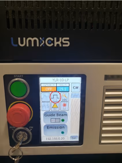
This guide provides step-by-step instructions for resolving cases where the trapping laser cannot be turned on because the interlock is not triggering. It covers checks for the trapping laser control unit, Emergency Off (EMO) button, power supply, and C-Trap hood closure. It also explains how to adjust the actuator block on the C-Trap door if needed.
This guide provides step-by-step instructions for resolving cases where the trapping laser cannot be turned on because the interlock is not triggering. It covers checks for the trapping laser control unit, Emergency Off (EMO) button, power supply, and C-Trap hood closure. It also explains how to adjust the actuator block on the C-Trap door if needed.
This guide describes when and how to power cycle or fully shut down the C-Trap. Power cycling can resolve common software or hardware errors, while full shutdowns are recommended for extended periods of inactivity. Step-by-step instructions ensure safe operation and provide guidance for troubleshooting.
This guide describes when and how to power cycle or fully shut down the C-Trap. Power cycling can resolve common software or hardware errors, while full shutdowns are recommended for extended periods of inactivity. Step-by-step instructions ensure safe operation and provide guidance for troubleshooting.
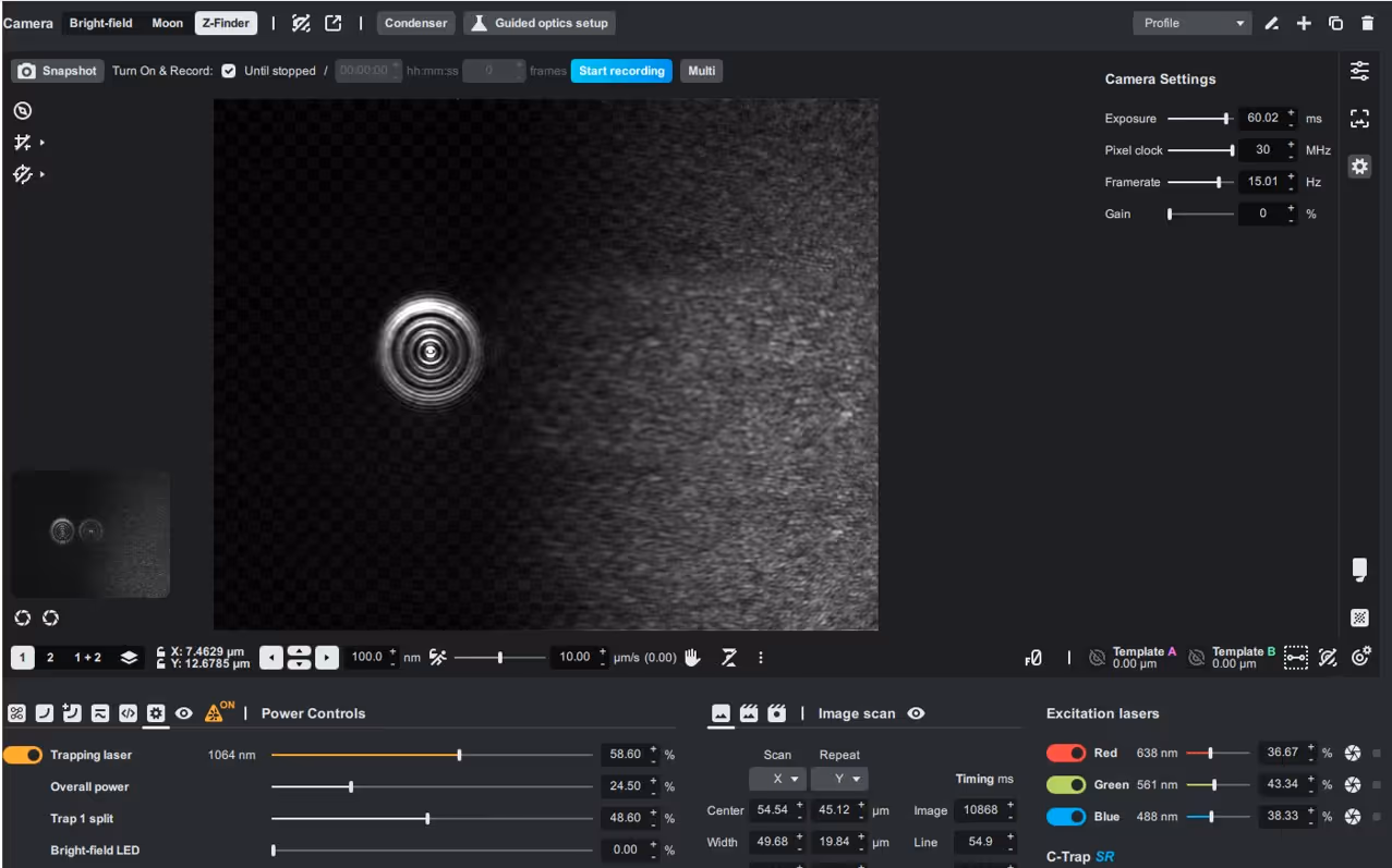
This guide details how to recover Trap 2 in the C-Trap system when it is out of view. It uses Z-finder camera focus, joystick movement, and step-size adjustments to locate and center the trap based on back reflections. The same guide can be used to find Traps 3 and 4.
lost trap, Z-finder, back reflection, trap recovery, step size, joystick control