Abstract
This guide provides step-by-step instructions for safely exchanging the microfluidic flow cell in your C-Trap. It includes preparation, removal of the existing flow cell, handling of tubing and ferrules, cleaning procedures, correct installation of a new flow cell, and final leak testing. Correct ferrule placement and use of a star-pattern tightening sequence are emphasized to ensure proper sealing and reliable operation.
1. Preparation
- Run a cleaning protocol on the current flow cell before beginning the exchange.
- While cleaning is in progress, prepare a clean workspace and collect the following materials:
- Small container for ferrules
- Tube cutter or guillotine (included in your C-Trap connection kit)
- Kimwipes
- Ethanol or isopropanol (IPA)
- Clean gloves
Once the cleaning protocol is complete:
- Flush ethanol through the flow cell. The residual ethanol will evaporate once the cell is removed.
- In the uFlux applet or Bluelake, stop the flow by closing the valves and vent pressure from the Autofluidics module.
2. Removal of the Existing Flow Cell
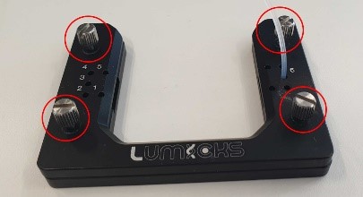
- Slightly loosen the four corner screws of the flow cell holder (Fig. 1, red circles).
- Remove the tubing by gripping each tube as close to the holder as possible and pulling upward.
- Tubing can sometimes be stuck, especially if it has not been removed before. Steady upward force works best.
- Loosen the four corners' screws a little more if the tubing is difficult to remove.
- If the tubing stretches, trim the stretched section with the black guillotine from the spare parts box.
- If it is still very difficult to remove, leave the tubing on and proceed to the next steps.
- Loosen the thumbscrews (Fig. 1, red circles) counterclockwise. Do this by hand; a screwdriver should only be used if absolutely necessary. The loose screws can stay in their place or can be removed and put in a safe area to be used later.
- Separate the top and bottom halves of the holder.
- Collect the white ferrules and place them immediately in the prepared container. They are small and easy to misplace.
- To remove the ferrules from the tubing (in the case that tubing of some channels has not been removed yet), push the tubing gently through the holder until the ferrules pop out at the back, then pull them off by hand (Fig. 2).
- If clogging has been an issue, cut the last few millimeters of tubing with the guillotine to expose a clean, open end.
- Remove the flow cell from the base of the holder (Fig. 3). Wipe the cell with ethanol/IPA to remove residues and allow residual ethanol to evaporate fully before storing.
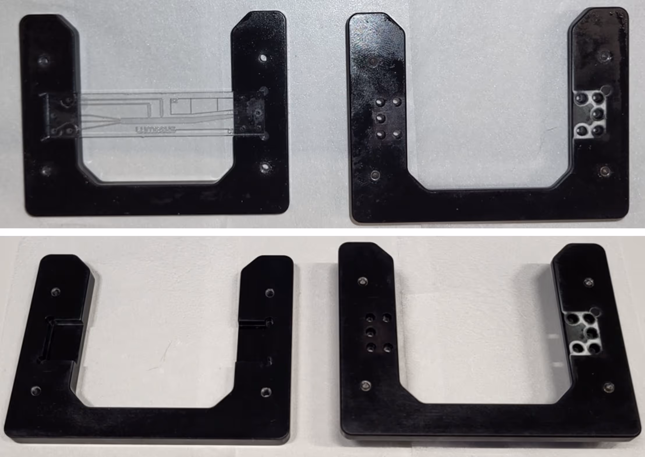
3. Installation of the New Flow Cell
- Place the new flow cell on the base (lower half) of the holder.
- Insert the ferrules into the openings in the upper half of the holder.
- Channels 1–5 are on the left-hand side.
- Channel 6 is on the right-hand side.
- Take this opportunity to clean the inside of the holder with ethanol/IPA and dry it completely before reassembly.
4. Reattachment of Tubing
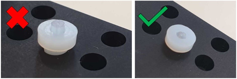
- Insert the tubing for Channels 1-5 into each of the corresponding holes in the flow cell holder, making sure each is secured in the ferrule:
- The wide end of the ferrule should face the cut end of the tubing.
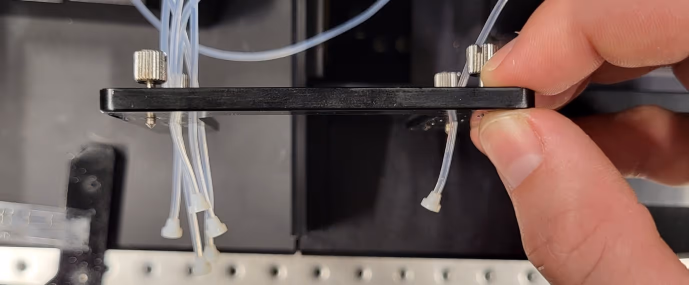
- The tubing tips should be flush with the ferrule face and not protruding (Fig. 4).
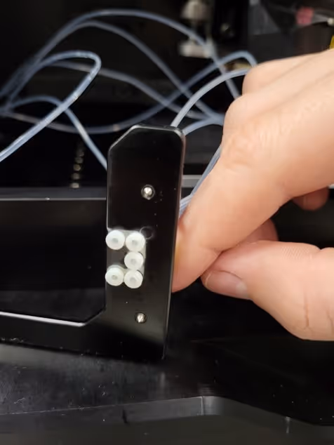
- Press the ferrules firmly back into the upper holder (see Fig. 5).
5. Securing the Flow Cell Holder
- Engage the thumbscrews by hand. Do not use a screwdriver for tightening.
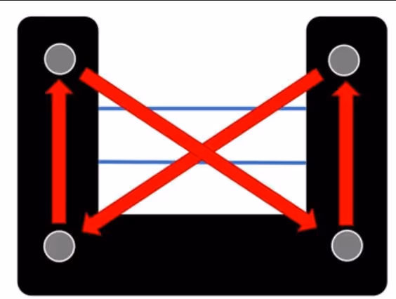
- Tighten the screws in a star pattern (Fig. 6):
- First, tighten two opposite corners until slight resistance is felt.
- Then tighten the remaining two corners equally.
- Finally, continue tightening gradually in the star sequence until the top and bottom halves are flush with no visible gaps.
- Avoid overtightening. The halves must be firmly sandwiched, but the screws should remain loose enough to be undone by hand during the next exchange.
6. Leak Test and Final Flush
- Flush Milli-Q water through the system at 2 bar for 2–3 minutes.
- This removes air bubbles and checks for leaks.
- Inspect carefully for fluid leakage between the upper and lower halves of the holder.
- If leakage is detected, tighten the screws slightly further in the star pattern.
- If leakage persists, repeat the assembly steps to verify correct tubing and ferrule placement.