
Uneven flow or clogging
Background & Diagnosis
In some cases, uneven flow may not be an issue. It just means that longer flushing time is needed. However, in many cases, it is an issue because the laminar layers’ dimensions may no longer be symmetric, which can significantly impact the workflow. Uneven flow could also be a sign of liquid spilling. In some cases, a channel can also be fully clogged, preventing samples from reaching the flow cell.
An uneven flow or clogging is most commonly noticeable by visually inspecting the syringe levels during large volume flows (e.g. cleaning or preparation). If the syringes show unexpected differences in volumes (fig. 1, left), then it is likely that the flow is partially clogged or that there is a leak in one or more channels. During the experiment itself, when looking at the bright-field, the presence of very large objects (e.g. large bubbles or precipitate) or the unexpected flow pattern of smaller objects (e.g. beads) can also indicate uneven or clogged flow.
Solutions
The steps below are ordered in their level of disruptiveness for the continuation of your experiment. Step 1a is the least disruptive and often allows you to continue your ongoing experiment. Step 4 is the most disruptive, requiring a full cleaning procedure and a complete stop of the experiment for the day. Continue sequentially through the steps until the problem is solved. In some cases, uneven flow or clogging is identified before the experiment begins, in contrast to midway through the experiment. In these cases, it is strongly recommended to fully solve the issue before starting the experiment. If the problem persists after all the steps, contact support@lumicks.com
- Initial troubleshooting without touching the condenser or objective:
- a. Inspect leaks near the syringes and valves (fig. 1, right). If there are visible leaks, skip directly to step 3
- b. Through the bright-field, inspect for large objects in the sample area (fig. 2) by moving the microstage. This information is often useful for further steps.
- c. If it is possible to flush at 2.0 bar without affecting the assay, flush at 2.0 bar the suspected clogged channel alongside other horizontal channels for 20s. Precious samples can be saved temporarily by exchanging the syringe’s content with buffer. Important: flushing at 2.0 bar can affect the passivation of the channel walls.
- d. Manually plunge the suspected clogged channel to increase pressure. Save the sample temporarily if need be (as in step 1c). Vent the pressure, then open both the suspected channel (e.g. channel 1) valve and waste channel (i.e. channel 6) valve. Disconnect the syringe of the corresponding channel and firmly push the content with the plunger (fig. 3). Look at the bright-field to check for signs of clogging (big bubble, or aggregates, flushing by, fig. 2). After a few seconds, you should see liquid drops falling out of the waste tube (if not, the channel is likely clogged)
- Further troubleshooting after raising the condenser and lowering the objective:
- a. Raise the condenser and lower the objective. Visually inspect for leaks near the flow cell tube connections. If there is a leak, clean up the leak, skip to step 3 and continue from there
- b. Visually inspect the flow cell for any visible blockage (large particle or bubble, fig. 4). If there is no visible blockage, proceed to step 2c. If there is a visible blockage, refer to the next section on “bubbles in the flow cell”, in step 3
- c. Disassemble the tubing of the suspected channel section by section, starting from the flow cell connection point first (fig. 5). Once the end is exposed, open the channel valve and manually plunge the plunger (fig. 3) while inspecting the open tube end. A droplet should easily form (fig. 6). If not, cut 0.5 cm off the end using the provided tube cutter (fig. 7, with proper orientation and angle) and see if that improves the flow
- d. Repeat step 2c at the valve upstream connection point (fig. 5)
- e. Additionally cut 0.5 cm at the syringe connection and the valve’s downstream connection (fig. 5)
- Replacing of suspected problematic component(s) (see "How to replace syringe, valves and tubing"):
- a. Based on steps 1 and 2 above, you should have a good idea of which component in which section of the system is problematic. Disassemble and reassemble the problematic component following instructions, and check if the flow improves
- b. Replace the suspected syringe, connection components, valve, or tube
- c. If you suspect the problematic component is the valve, there could also be a mechanical failure where the valve no longer opens, in which case, follow "Autofluidics unit troubleshooting"
- Full cleaning protocol available on LUMICKS Store. Note: ACR is usually much more effective than CR at removing bubbles, aggregates and other objects from the flow cell.
Bubbles in the flow cell
Background & Diagnosis
Bubbles in the flow cell should be avoided. Bubbles can cause uneven flow and can change the laminar boundaries of the channels, and while they may be out of the assay area, their existence up stream or downstream may induce pressure waves (air expanding and shrinking) that the beads will feel. This is especially evident under flow. Without flow, these fluctuations may still impact sensitive experiments.
In most cases, bubbles are directly visible in the flow cell during sample set up (fig. 4). They can also be visible in the bright-field camera during the experiment (fig. 2, right). In some cases, the presence of a bubble can also be guessed based on very unexpected laminar flow patterns (fig. 2, left).
Solutions
The steps below are ordered in their level of disruptiveness for the continuation of your experiment. Step 1 is the least disruptive and often allows you to continue your ongoing experiment. Step 4 is the most disruptive, requiring a full cleaning procedure and a complete stop of the experiment for the day. Continue sequentially through the steps until the problem is solved. In some cases, bubbles are identified before the experiment begins, in contrast to midway through the experiment. In this case, it is strongly recommended to fully solve the issue before starting the experiment. If the problem persists after all the steps, contact support@lumicks.com
- Estimating the impact and risk of the existing bubble(s) without troubleshooting:
- a. Is the bubble disruptive for the current experiment? Is there a way around the bubble? Bubbles can be tricky to remove, especially in channels 4 and 5. Troubleshooting can potentially lead to more complications and sometimes, to a full arrest of the experiment. Consider workarounds depending on how risky it is to remove the bubble. For example, if the bubbles are in channel 4, but channel 5 is still free, one may consider to leave them untouched and continue the work in channel 5 instead. Keep in mind that the bubbles may grow, especially if the traps are nearby, or also overtime
- Initial troubleshooting without touching the condenser or objective:
- a. If it is possible to flush at 2.0 bar without affecting the assay, flush at 2.0 bar the channels where the bubbles are, alongside other horizontal channels for 20s. In most cases, the bubble will be in the main channel area (fig. 5). Precious samples can be saved temporarily by exchanging the syringe’s content with buffer. Important: flushing at 2.0 bar can affect the passivation of the channel walls.
- b. Through the bright-field, inspect the sample area for bubbles (fig. 2) by moving the microstage. This information is often useful for further steps.
- c. Manually plunge one of the first 3 channels for even more pressure. Typically, the buffer channel 3 is chosen to avoid spreading the content of channels 1 and 2 throughout the flow cell. Save the sample temporarily if need be (as in step 2a). Vent the pressure, then open both the selected channel (e.g. channel 3) valve and waste channel (i.e. channel 6) valve. Disconnect the syringe of the corresponding channel and firmly push the content with the plunger (fig. 4). Look at the bright-field to check for signs of bubbles flushing by (fig. 2). If successful, you should see several bubbles pass by over 5-10s.
- Further troubleshooting after raising the condenser and lowering the objective:
- a. Raise the condenser and lower the objective. Visually inspect for bubbles in the flow cell. If there are no visible bubbles, the unexpected flow patterns may come from uneven flow or clogging of the channels. Refer to the “Uneven flow or clogging” for troubleshooting steps. If there are visible bubbles, continue to step 3b below. At this point, any following steps may create even more bubbles in the flow cell especially when there is BSA or surfactants in the buffer. If that is the case, you may have to perform step 4 below, completely stopping your experiment for the day.
- b. While flushing all channels at 0.5 bar, gently pull the waste tube out of the flow cell (fig. 8). This will generate a pressure wave moving outwards, that will likely dislodge or split the bubbles. Pushing the exit tube back in will generate another pressure wave, this time inwards, while also likely generating a new bubble. Unplugging and plugging the waste tube gently can generate different pressure waves that may get rid of the flow cell bubbles. Important: never pull or push on the tubing connection while the pressure is higher than 0.5 bar, this may rupture the flow cell. Unplugging and plugging of the tube may be difficult. If too much force is required to do this, to the point where the tube is deformed, loosen the flow cell holder screws (see "How to replace syringe, valves and tubing") and try again. If deformed, make sure to cut the corresponding tubing tips properly before inserting it back into the flow cell (fig. 7).
- c. After having generated a few pressure waves, plug the tubing back, then flush at 2.0 bar (as in 2a) or manually plunge (as in 2c) to see if the flow now can push the bubbles out
- d. Repeat this unplugging and plugging process with one of the first 3 channels, while also alternating with some high-pressure flows or manual plunges in between. In this case, purposefully generating a bubble upstream while plugging in the tube may also push the other bubbles downstream
- Full cleaning protocol available on LUMICKS Store. Note: ACR is usually much more effective than CR at removing bubbles from the flow cell.'
Figures
Figure 1: unexpectedly low volume (left) and leakage (right) visible

Figure 2: bright-field image showing unexpected flow pattern in the flow cell (left, curved flow) and a bubble (right)
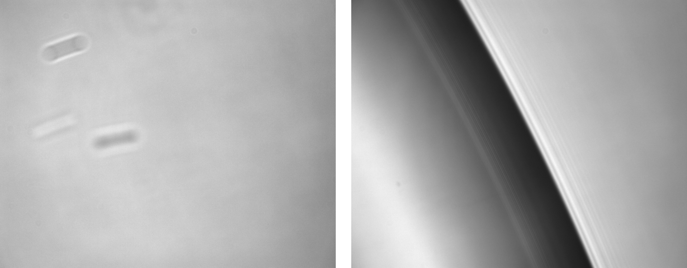
Figure 3: how to manually push the syringe with its plunger

Figure 4: visual inspection of the flow cell can reveal flow obstructions or bubbles (in this case)

Figure 5: removal of the tube of channel 1 at the flow cell connection point (left). The valve’s upstream connection point (pink circle), the syringe’s connection point (yellow triangle) and the valve’s downstream connection point (blue square) are indicated (right)

Figure 6: droplet formation at the open tube end
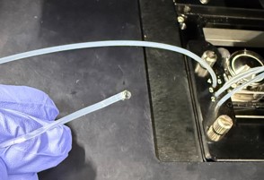
Figure 7: tube cutter (left) and cutting of ~0.5 cm of tubing

Figure 8: tube cutter (left) and cutting of ~0.5 cm of tubing

